


Products Description
Тестер продольной водопроницаемости геосинтетических материалов TGHCE-2 подходит для различных типов дренажных лент и дренажных полотен (плит).
Тестер продольного расхода воды для геосинтетических пластиковых дренажных полос
Модель: TGHCE-2
I. Введение в продукт:
Тестер продольной водопроницаемости геосинтетических материалов TGHCE-2 разработан и изготовлен компанией Hebei Tianqixingzi Inspection Equipment Co., Ltd. на основе национальных отраслевых стандартов JTG E50-2006 «Процедуры испытаний геосинтетических материалов в дорожном строительстве» и T1143-2006 «Испытание предела текучести при сжатии и водопроницаемости сердечника пластикового дренажного пояса». Он также соответствует стандартам ISO 12958-1:2020, ISO 12958-2:2020, ASTM D4716/D4716M-22 и пригоден для экспорта.
II. Структурное описание:
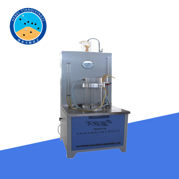
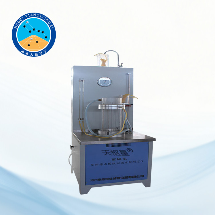
1. Данное изделие состоит из: рабочего контейнера, переливного балансировочного бака, бака насоса высокого давления, расположенного внутри левой дверцы, интеллектуального счетчика контроля давления, медной трубы для создания давления, датчика давления, насоса для создания давления, манометра, сливной трубы, входного балансировочного бака, трубы подачи воды, интеллектуального счетчика с таймером, водозаборника, переливного бака для подачи воды, индикатора уровня воды, сливного патрубка и насоса подачи воды.
2. Пластиковый ленточный (пластинчатый) тестер расхода (см. рисунок). Он изготовлен из нержавеющей стали и состоит из восьми основных компонентов: рабочего резервуара, резервуара для создания давления, переливного балансировочного бака, входного балансировочного бака, входного напорного бака, переливного бака для подачи воды, электрического насоса для создания давления и электрического насоса для подачи воды.
3. Рабочий контейнер приварен из цилиндра из нержавеющей стали диаметром 130 мм и толщиной стенки 2 мм к фланцу диаметром 200 мм и толщиной стенки 10 мм, эффективной длиной 40 см. В центре фланца просверлено эллиптическое отверстие диаметром 120 мм × 15 мм, а заподлицо с нижним краем отверстия установлен перфорированный опорный поддон из нержавеющей стали. Рабочий контейнер снабжен манометром, сливным патрубком (с клапаном), входом давления (с регулирующим клапаном), входом воды (с клапаном) и переливным патрубком (с клапаном).
4. Входной балансировочный бак имеет высоту 30 см и приварен к фланцу целиком с помощью горизонтального соединительного профиля размером 150 мм × 40 мм. Отверстие фланца соответствует фланцу сосуда под давлением. Входное отверстие установлено на высоте 10 см в баке. Внутри бака установлен переливной порог высотой 25 см (от дна бака), а переливное отверстие 1 установлено снаружи входного балансировочного бака.
5. Переливной балансировочный бак имеет высоту 7 см и приварен к фланцу целиком с помощью горизонтального соединительного профиля размером 150 мм × 40 мм. Отверстие фланца соответствует фланцу сосуда под давлением. Внутри бака установлен переливной порог высотой 5 см (от дна бака), а переливное отверстие 2 установлено снаружи переливного балансировочного бака.
III. Информация о продукте:
Пластиковые дренажные ленты (плиты), также известные как геополимерные дренажные ленты или пластиковые плиты, представляют собой широко используемый полосообразный дренажный материал. Их ширина поперечного сечения составляет приблизительно 10 см, а толщина — приблизительно 5 мм. Основные показатели качества включают прочность на растяжение композитной и фильтрующей мембраны, а также продольный расход воды, соответствующие стандартам JTS-206-1-2009 «Пластиковые дренажные ленты (плиты) для водоотведения», JTGESO-2006 «Геосинтетические материалы для дорожного строительства» и S1235-2012 «Геосинтетические материалы».
Данный продукт был разработан и изготовлен нашим заводом по запросу Центра контроля качества Национального бюро строительных материалов. Эксплуатационные испытания, проведенные центром контроля качества, подтвердили рациональность конструкции и соответствие всех показателей проектным требованиям. Это специализированный испытательный прибор для проверки продольного расхода воды в пластиковых дренажных лентах (плитах).
IV. Технические характеристики изделия:
1. Размер образца: 100 мм × 450 мм
2. Напряжение питания: 380 В
3. Вес: 220 кг
4. Габаритные размеры: 1040 × 660 × 1300 мм
V. Принцип работы:
Вода из переливного бака перекачивается в рабочий контейнер с помощью водяного насоса, заполняя его водой. Затем запускается насос для создания давления в контейнере под давлением. Давление воды контролируется интеллектуальным счетчиком давления, и контейнер под давлением передает давление в рабочий контейнер для балансировки давления.
VI. Инструкция по установке:
1. Установка образца
Разрежьте образец на отрезки длиной примерно 48 см. Удалите по 1 см фильтрующей мембраны с каждого конца. Снимите фаску с четырех углов образца под углом 45° и аккуратно вставьте его в трубчатую латексную мембрану.
Пропустите дренажную ленту (пластину) вместе с латексной мембраной в рабочий контейнер через отверстие. Вытолкните ее вдоль опорной пластины через другое отверстие, обеспечив примерно 4 см открытой длины с обоих концов фланца.
Используйте резиновые прокладки, чтобы закрыть открытую часть дренажной ленты (пластины), убедившись, что прокладки плотно прилегают к внешней стороне фланца. Переверните латексную мембрану поверх резиновых прокладок. Закройте оставшуюся открытую часть дренажной ленты (пластины) еще двумя резиновыми прокладками, зажав перевернутую часть латексной мембраны между прокладками. Фильтрующая мембрана дренажной ленты (пластины) должна выступать за пределы резиновых прокладок.
Закрепите входной и переливной балансировочные баки на рабочей емкости четырьмя винтами, равномерно затянув их.
2. Подача воды: Откройте водяной насос и впускной клапан 3, чтобы заполнить водобалансировочный бак водой через входное отверстие, позволяя воде вытекать через переливное отверстие 2 переливного балансировочного бака в течение некоторого времени, чтобы удалить воздух из дренажной ленты (пластины) и полностью смочить фильтрующую мембрану. Затем закройте впускной клапан 3.
3. Прессование (нагнетание давления)
Откройте сливной и впускной клапаны рабочего контейнера, включите насос подачи воды и подавайте воду через впуск до тех пор, пока она не начнёт вытекать из сливного отверстия. Затем закройте впускной и сливной клапаны и включите насос нагнетания давления. Повышайте давление до заданного значения — после этого установка автоматически остановится.
Из-за деформации дренажной ленты (пластины) давление будет снижаться. При необходимости выполняйте дополнительное нагнетание до стабилизации давления. Время, необходимое для этого процесса, зависит от прочности сердечника и фильтрующей мембраны дренажной ленты (пластины) и обычно составляет от 0,5 до 2 часов.
4. Испытание на расход воды
Откройте входное отверстие, чтобы вода стекала через переливные отверстия 1 и 2. В этот момент разница уровней воды между двумя концами дренажной ленты (пластины) должна составлять ровно 20 см, с гидравлическим градиентом 0,5. Проверьте, соответствует ли давление 350 кПа. После того, как все соответствует требованиям, с помощью мерного цилиндра измерьте расход воды в переливном отверстии 2 и температуру воды. Расход воды измеряли повторно через 6 часов. Когда относительная погрешность между двумя измерениями составляла менее 2%, последний показатель расхода воды принимали за значение, полученное в ходе испытания для данной дренажной ленты (пластины).
В каждой группе испытывали две дренажные ленты (пластины), и среднее значение двух измерений принимали за расход воды в этой группе.
VII. Требования к установке:
Питание подается по трехфазной четырехпроводной системе. Зеленый провод — это провод заземления, а остальные три могут быть подключены произвольно.
VIII. Обеспечение качества:
1. Пользователи могут проконсультироваться по техническим вопросам через горячую линию послепродажного обслуживания и получить четкие решения.
2. В случае возникновения сбоев в работе при нормальной эксплуатации наша компания гарантирует предоставление вышеуказанного гарантийного обслуживания. Кроме того, если применимые национальные законы и правила предусматривают иное, наша компания будет соблюдать соответствующие законы и правила.
3. В течение гарантийного периода следующие ситуации подлежат платному ремонту:
(1) Повреждения, вызванные человеческим фактором или форс-мажорными обстоятельствами;
(2) Неисправности или повреждения, вызванные неправильной эксплуатацией;
(3) Неисправности или повреждения, вызванные модификацией, разборкой или сборкой изделия;
(4) Невозврат товара в течение одного месяца в соответствии с условиями «Обязательства по послепродажному обслуживанию», указанными на этой странице.